Network Settings
The Network Settings application allows administrators to configure various aspects related to the Crystal Eye XDR network. One of the major features of this app is that it provides a user centric platform to segment and segregate the network.
Network segmentation and segregation is a fundamental network strategy that can be implemented to reduce the impact of a possible intrusion. This can very well be understood with the help of the two diagrams below where we have an example of a segregated network and non-segregated network.
Segregated Network:
The segregated network below is divided into VLAN1 and VLAN 2. Due to this, there is a reduced impact post network intrusion and infection since only the host in VLAN2 gets infected and the host in VLAN1 remains unaffected.

Non-Segregated Network:
The diagram below shows how a non-segregated network or flat network can cause all the hosts in the network to be infected.

The Australian Cyber Security Centre (2019) explains network segmentation well in their write up on the topic:
“Network segmentation involves partitioning a network into smaller networks; while network segregation involves developing and enforcing a ruleset for controlling the communications between specific hosts and services.”
Historically network segmentation and segregation has been achieved with a gateway firewall at the network perimeter; or by creating a segregated environment of trusted and untrusted zones in the case of a demilitarised zone. This is however what we call a flat network since this setup still consisted of a single segment, which allowed widespread access after only a single intrusion by an adversary.
The advanced threats we are seeing today render this kind of setup ineffective and accentuate the importance of not only segregation of networks, but also proper segmentation.

Granular Control Over the Network: Network Segmentation and Segregation allows greater control over different areas of the network. It becomes possible to enforce firewall policies and secure network traffic once the much-needed control is established over various levels of the network.
Enhanced Traffic Flow: With fewer hosts in each segregated network the local traffic is minimised reducing congestion and boosting the performance of the network traffic flow.
Increased Operational Control: A well segmented network ensures greater levels of operational control over the technical and business processes aligned to the systems deployed in the network.
Increased Security Control: Once the network is segregated into smaller subnets it becomes easier to identify the areas which requires security controls assigned to it. This further helps in elevating the security posture of the organization.
Minimise Attack Surface: Achieving greater levels of increased operational control and security control through network segmentation has a direct impact on reduction the attack surface.
Better Policy Control: Having small subnets for various departments and business processes ensures the possibility of greater network visibility and a tight grip on the network resulting to better policy control.
Risk Compliance: Network segmentation facilitates clarity in understanding the flow of traffic and internal assets. Such an understanding of the network helps to access the risk levels aligned to each segmented network.
Network segmentation caters for different levels of Risk Appetite between departments.
To apply network segmentation and segregation successfully, the implementation must be driven by a proper security-based network architecture which also caters for the organisational requirements. The network architecture should cater for network security technologies such as Zero Trust.
Zero Trust Network Access (ZTNA): Zero Trust Network Access (ZTNA) is a set of network access technologies deployed at the perimeter of a network that operates on an adaptive trust model that starts with no one is trusted and access is granted on a need-to-know or least privilege basis, defined by granular policies.
Network segregation assists with Zero trust: Authorising and authenticating users and deny access to segments they should not have access to and monitor internal networks as closely as external.

The table above shows Red Piranha’s seven key security outcomes and how they map to relevant sections of the ISO 27001, NIST and COBIT 5 frameworks for example. Network Segmentation and Segregation falls under third one on the list, namely Identity and Access Management.
The following table maps the seven key security outcomes to Red Piranha’s services and technologies (including network segmentation as a service):

The Network Settings application is installed by default and can be accessed from the left-hand navigation panel.
Left-hand Navigation Panel > Network Control > Infrastructure > Network Settings |
|---|
The Add Interface feature of the Network Setting application allows users to create three types of interfaces namely, Virtual, VLAN and PPPoE.
IMPORTANT: Crystal Eye XDR caters for Network Segmentation and Segregation through the configuration of Zones, Interfaces, and Rules.
The Network Settings application deals with foundation of this process, namely the interfaces. Each interface being created is a separate network which can be assigned its own subnet. Interfaces can be added to zones in this section or in the Advanced Firewall section under zones. An interface can be assigned to multiple zones.
A virtual interface can be created on an existing ethernet interface (any of the WAN interface) and can be made to be a recipient of traffic targeted towards a host or server in the Crystal Eye XDR network.
The following scenario explains how a virtual interface can be created and effectively used as per the business use case:

In the above diagram, ABC Pvt Ltd. has a webserver with a private IP address 192.168.1.2. This web server is deployed in a CE XDR network. The CE XDR administrator Alfred wants to ensure that this web server is publicly reachable through a virtual interface created over the WAN interface. WAN interface here is the ethernet interface.
This is essentially a 1-to-1 NAT setup with a Virtual Interface over the WAN interface. Henceforth, we will also have to create a 1-to-1 NAT rule using the Application Rules feature of the Advanced Firewall application.
Note: To make this set-up work, the virtual interface that we intend to create here must have a static IP address of the same range of that of the WAN interface.
On completing the above-mentioned settings, all users from the WAN side will be able to access the web server through the Virtual Interface set-up over the WAN1 interface. This also means that the WAN1 interface of the CE XDR will be disabled, and the Virtual interface created over WAN1 will be made to answer to all incoming traffic directed to the web server.
Let’s perform the steps discussed above to make a web server assigned with a private IP address accessible publicly through a virtual interface created over WAN1 interface of the CE XDR.
Note: By pursing the following steps you will understand how to create a Virtual Interface on the CE XDR and the functionalities related to it.
Step 1: In the Network Settings application, click the Add Interface icon in the Interfaces section next to WAN1.

Step 2: You will now see the Add Interface page. Select Static from the Protocol dropdown.

Note: A virtual interface must be given a static IP address and should use the same subnet as the existing WAN interface IP address. Henceforth, we shall select the Protocol as Static from the protocol dropdown.
Step 3: Select the Zone as WAN from the dropdown.

Step 4: Enter the IP address of the Virtual Interface in the IP address text box.

Note: Ensure that the IP address that is being manually assigned to the virtual interface is on the same range as the WAN interface IP address of the Crystal Eye XDR. In our case the WAN1 IP address (WAN interface IP address) of the CE XDR is 173.208.246.243. Henceforth, we shall assign the IP address of the virtual interface as 173.208.246.244.
IMPORTANT: The CE XDR administrator can also assign a maximum transmission unit (MTU) in the designated text box. The is the size of the largest protocol data unit (PDU) that can be communicated in a single network layer transaction. The default MTU value set in the CE XDR backend is 1500. However, this default value can be adjusted. Larger MTU is associated with reduced overhead. Smaller MTU values can reduce network delay.
Step 5: Enter the Index in the text box, assign a Metric value, assign the Gateway and click the Add button.

Note I: The Metric Value of the is assigned to prioritize the routes for the traffic. It is recommended to assign a higher metric value for the virtual interfaces.
Note II: Ensure that the gateway IP is identical to what was assigned to the WAN interface over which the current virtual interface is created.
Note III: You will now be directed to the Interfaces section where you’ll see the virtual interface that has been created. 
Step 6: Disable the WAN1 interface using the enable/disable button.

Now that the Virtual Interface has been successfully created, we will create a 1-to-1 NAT rule in the Application Rules section so that the web users can access the website running on the web server behind the CE XDR.
Step 7: Go to Security Configuration > Advanced Firewall > select the Application Rules tab and click the Add button under the Rules section.

Step 8: You will now see the Add New Application Rule pop-up box.
- enter the description of the application rule,
- select the Port as Any from the dropdown,
- select the From IP Address from the dropdown under the DNAT section (in our case we will select 171.208.246.244 which is also the WAN1_VIRTUAL Interface IP address),
- enter the To IP Address in the text box under the DNAT section (in our case we will enter 192.168.1.2 which is the IP address of the web server in the CE XDR network)

Step 9: Click the Advanced Settings tab.

Step 10: You will now see the Advanced Settings page.
- Select the Source Zone as WAN
- Click the Add button

Note: You will now be directed to the Rules section where the 1-to-1 NAT rule will get displayed.
Crystal Eye XDR when deployed as a gateway firewall can be configured to have Virtual LAN interfaces. Creation of VLANs in the CE XDR network helps in network segmentation such that it facilitates creation of multiple logical LAN segments within the LAN Ethernet Interface and each logical LAN segment uses its own IP subnet.
These logical LAN segments also known as VLANs helps in:
- elevating network security,
- improve network performance,
- reduce costs,
- improve network throughput, and
- facilitate a favourable platform to assign advanced firewall rules.
Note: To ensure that VLAN works in the CE XDR network set-up, the appliance must be connected to another device which has the capability to understand VLAN configurations (for example a switch). We recommend configuring the switch in ‘trunking’ mode and specify a VLAN ID.
Broadcast Frames Handled in a Switch Before and After VLANs are created in the CE XDR Network
Broadcast frames are hexadecimal MAC address that are transmitted when network services make announcements to other hosts in the network.
Let’s first understand how broadcast frames are handled in the CE XDR network without VLANs through the scenario below. In the scenario below, the network has been segmented for 4 departments namely, development team, customer service team, finance team, and sales & marketing team. Each team has roughly 20 end-point devices (predominantly laptops). Based on the requirements, it was decided to route development team, customer service team, via switch A and the finance team, and sales & marketing team via switch B. To do this, the LAN traffic was processed through the 4 LAN ports of the Crystal Eye XDR which is running as on gateway mode in this network.

In the diagram above, if any given PC in the development team needs to communicate with the sales & marketing team the frames would be broadcasted to all the ports and the users connected to both switch A and switch B. Such a topology can create congested broadcast domains resulting in compromise in redundancy, load balancing and security.
In the scenario below, we shall understand how broadcast frames are handled in a network which is segregated using Virtual LANs. The departments development team, customer service team, finance team, and sales & marketing team have been segmented by creating 2 VLANs in each CE XDR LAN port. This will essentially result to the frame not being broadcasted beyond the VLAN boundary which will in-turn ensure less or no congestion in the network.

In the above diagram, PCs in the customer service team’s VLAN (VLAN 10) wouldn’t be able to communicate to any of the other VLANs of the company having a different VLAN ID. However, the customer service team’s VLAN (VLAN 10) would be able to communicate with the sales & marketing team VLAN (VLAN10). This kind of a topology will boost the performance and security of the network.
How to Create a VLAN in the Crystal Eye XDR?
The following steps can be pursued to create a VLAN in any LAN interface of the CE XDR:
Step 1: In the Network Settings application, click the Add icon next to LAN 1.

Step 2: You will now see the Add Interface page. Select VLAN from the Type dropdown.

Step 3: Select the protocol as Static.

Step 4: Select the Zone from the dropdown. We will select LAN in our case.

Note: Zone can be assigned to a particular VLAN and firewall policies can be aligned to the selected zone.
Step 5: Enter the IP address of the VLAN in the text box.

Step 6: Enter the VLAN ID in the text box and then click the Add button.

IMPORTANT: The CE XDR administrator can also assign a maximum transmission unit (MTU) in the designated text box. MTU is the size of the largest protocol data unit (PDU) that can be communicated in a single network layer transaction. The default MTU value set in the CE XDR backend is 1500. However, this default value can be adjusted. Larger MTU is associated with reduced overhead. Smaller MTU values can reduce network delay.
Note: The VLAN will get displayed at the Network Interfaces section. crystal-eye-xdr-create-vlan8
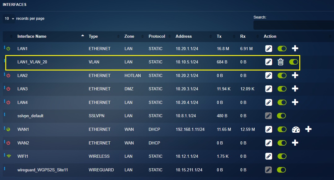
PPPoE is an authentication based broadband connection mostly used as a configuration for Digital Subscriber Line (DSL) circuits. The Crystal Eye XDR has user centric GUI controls which allows users to create a PPPoE interface over Physical interface.
How to Create a PPPoE Interface?
Step 1: In the Network Settings application page, click the Add button next to the WAN interface. In our case its we will create the PPPoE interface over the WAN 1 interface.

Step 2: You will now see the Add Interface page. Select PPPoE from the Type dropdown.

Step 3: Enter the PPPoE username and password in the text box and click the Add button.

Note: You will now see the PPPoE interface displayed in the Interfaces section.
PPPoE connections have a number of optional values that can be used to further tune PPPoE sessions for improved performance and stability
AC Name: (Access Concentrator Name) This is an optional setting that specifies the Access Concentrator (PPPoE Server) Name and restricts connections to the Access Concentrator matching the specified name. The default value is blank.
Service: (Service Name) This optional setting CE will only initiate PPPoE connections with Access Concentrators that provide the service specified in this field. The default value is blank.
Timeout: Time in seconds that the Crystal Eye waits for activity before assuming a link down and attempting reconnections. Default is to leave it as 4 x LCP Interval which is 80.
Clamp MSS: Clamp Maximum Segment Size Clamping the Maximum Segment Size prevents TCP connections from serving packets that are too large and reduces the risk of fragmentation. This is expressed in bytes and is calculated by taking the MTU value less the PPPoE header, IP header and TCP header sizes. The default value is 1412.
LCP Failure: Link Control Protocol Failure Threshold of failed LCP echo requests to assume a failed connection and terminate the connection before attempting to re-establish the PPPoE connection. Default value is 5.
LCP Interval: Link Control Protocol Interval Time in seconds between LCP echo requests when checking for failed connections. Default value is 20.
Connection Poll: Time in seconds between status checks of the PPPoE interface. Default is 6.
Connection Timeout: Time in seconds the Crystal Eye will allow a new PPPoE connection to complete before that the new connection was not successful and the Crystal Eye terminates the failed session and attempts to establish a new PPPoE session. Default value is 80.