High Availability
High Availability is a network deployment scenario where two Crystal Eye appliances can be used to provide uninterrupted access to the users in the event of link or node failure. Such a network configuration helps in creating a robust failover system wherein, if the primary CE fails to operate, the secondary CE automatically secures the network. Such a characteristic of the CE ensures agreed level of operational performance for a desirable period of time also known as High Availability.
There are certain pre-requisites to ensure successful deployment of a High Availability Set-up on Crystal Eye:
- Both the CE appliances should have the same release running for configuration and state synchronization.
- Both the CE appliances should be registered individually and should have valid licenses.
- Each CE appliance should have a dedicated port for state synchronisation with the peer.
- Each box should have a different internet hostname for configuring certificates.
Left-hand Navigation Panel > System Configuration > High Availability |
|---|
Configuring and setting up high availability on Crystal Eye can be divided into four main set of steps namely, Physical Set-up of High Availability in Crystal Eye, HA Settings & Configurations in Master CE and HA Settings & Configurations in Backup CE.
Note: The list of steps required to complete configuration process of high availability must be done in specific order. First set of steps is related to Physical Set-up of High Availability in Crystal Eye, the second set of sets involves HA Settings & Configurations in Master CE and finally the last phase deals with HA Settings & Configurations in Backup CE.
What is Master CE and Backup CE?
The Master CE forwards the traffic between the user network and the internet while the Backup CE works on a standby mode and waits for the Master CE to fail. When MASTER CE fails (either due to link failure or if CE comes down), traffic automatically uses the Backup CE. This ensures that the network is accessible despite failures with minimum traffic loss.
Note: The system configuration of the Master CE gets replicated to the Backup CE when the fail-over happens.
As if now, Crystal Eye supports Active/Passive High Availability. It’s a failover system mode of Crystal Eye where one of the two CE’s is selected as the Master CE and the other one is selected as Backup CE. The Master CE forwards the traffic between the user network and the internet while the Backup CE works on a standby mode and waits for the Master CE to fail. When MASTER CE fails (either due to link failure or if CE comes down), traffic automatically uses the Backup CE. This ensures that the network is accessible despite failures with minimum traffic loss.
In order to physically set-up High Availability in Crystal Eye, two CE appliances are required to be connected to each other through a dedicated peer link. This dedicated peer link is established by connecting LAN 2 ports of both the CE’s. Apart from this, both the CE appliances must be connected to the internet externally and a LAN network internally. As recommended below, both the CE’s are connected to the internet through its WAN 1 ports and to the LAN network through its LAN 1 ports.
The recommended physical set-up of high availability in Crystal Eye is explained in the diagram below. 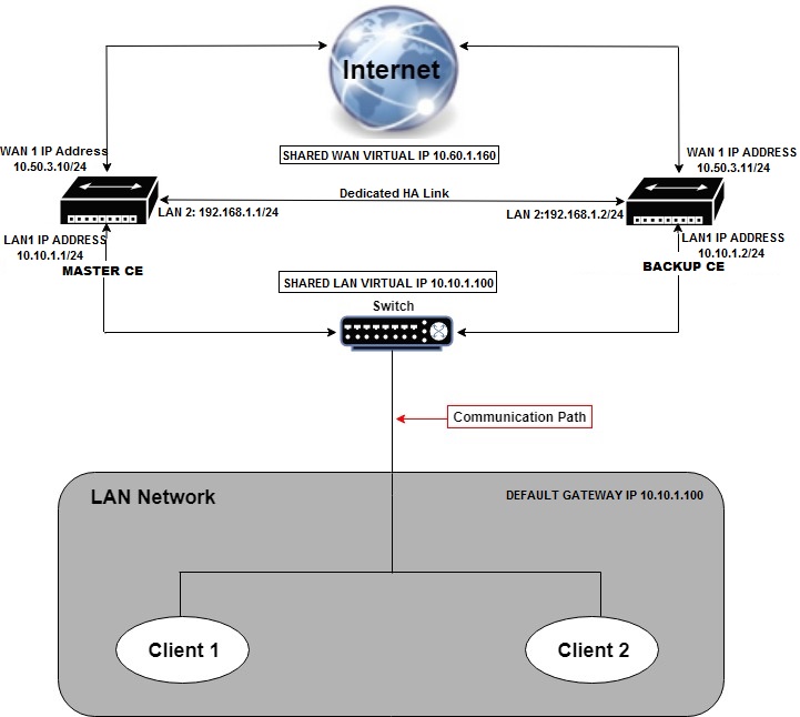
Once the two Crystal Eye appliances are physically configured to support High Availability, the administrator must choose which one of the two appliances must be selected as Master and Backup.
There are a string of settings that are done in the Master CE such as Selecting the HA State, Adding HA Link Interface, Adding Peer HA Link Address, Adding Peer HA Link Mask, Adding Monitoring Interface, Adding Floating IP Address and Adding Multiple Monitoring Interfaces.
How to Configure Master CE for HA Setup?
Step 1: In the High Availability page, click the edit button under the Global Settings section.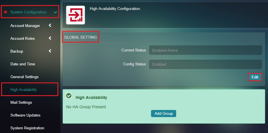
Step 2: You will now see the editable version of the Global Settings section. Select Enable from the Config Status dropdown and click the Update button.
Note: Once High Availability Configuration Status is Enabled, the HA icon in the top left corner of the navigation menu will turn green as shown below. However, if the HA Configuration status is disabled then the High Availability icon turns grey.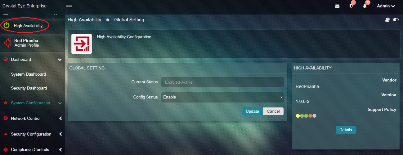
Step 3: In the High Availability application page of the Master CE, click the Add Group button.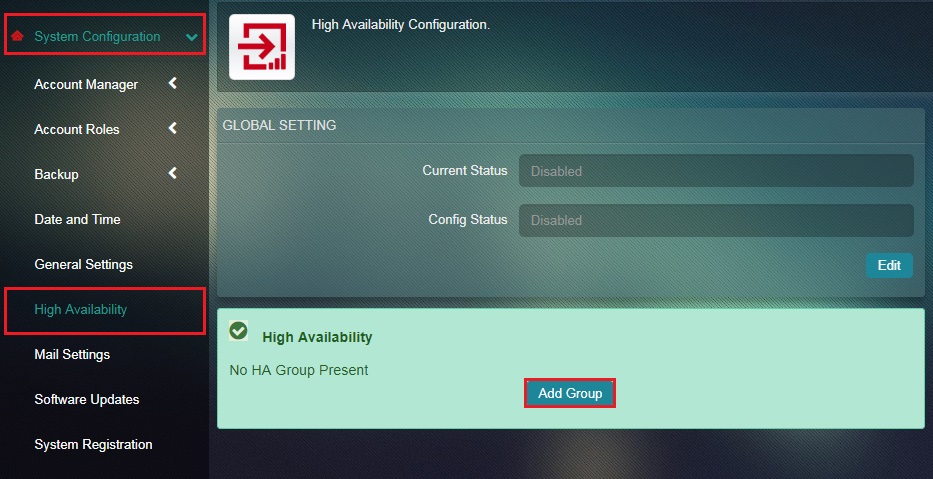
Step 4: You will now see the Add HA Group page. Select the HA State as Master from the dropdown.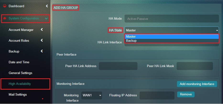
Step 5: Select HA Link Interface from the dropdown.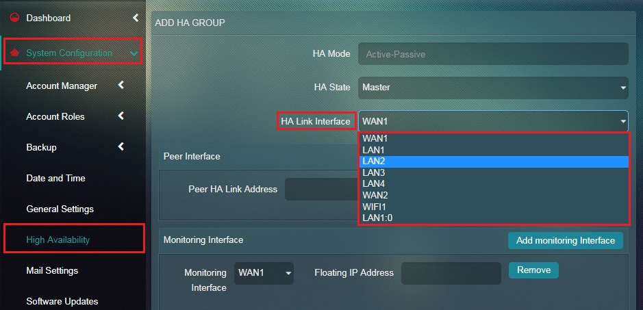
Note: The HA Link Interface is the dedicated link interface between the two CEs (in our case it’s LAN 2).
Step 6: Enter the Peer HA Link Address in the textbox under the Peer Interface section.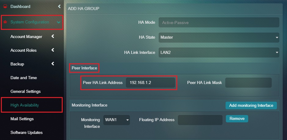
Note: The Peer HA Link Address here is the LAN2 IP address of the Backup CE which can be found in the IP settings application under the Network Interface section of the Backup CE. To know the Peer HA Link Address here, navigate to Network Control (in the Backup CE) > Infrastructure > IP Settings and view the LAN 2 IP address in the Network Interface section (highlighted below). In our case its 192.168. 1.2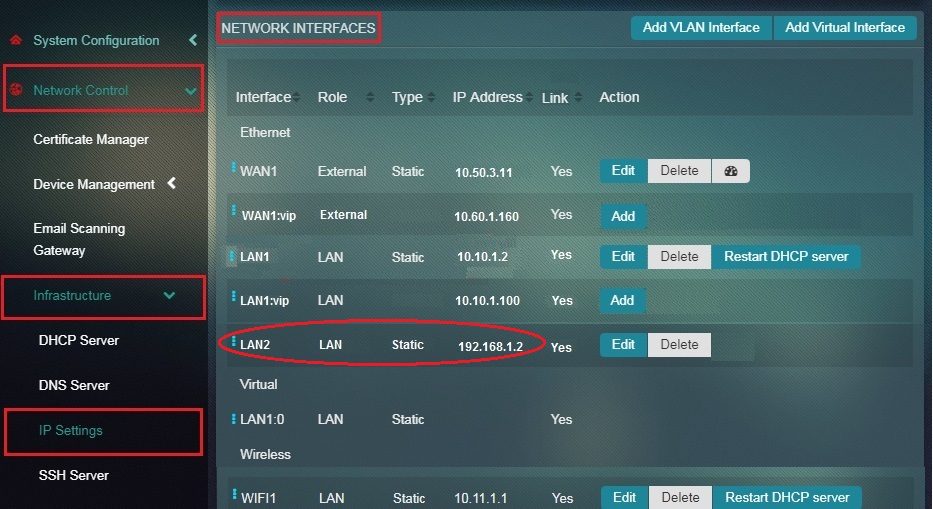
Step 7: Enter the Peer HA Link Mask in the textbox under the Peer Interface section.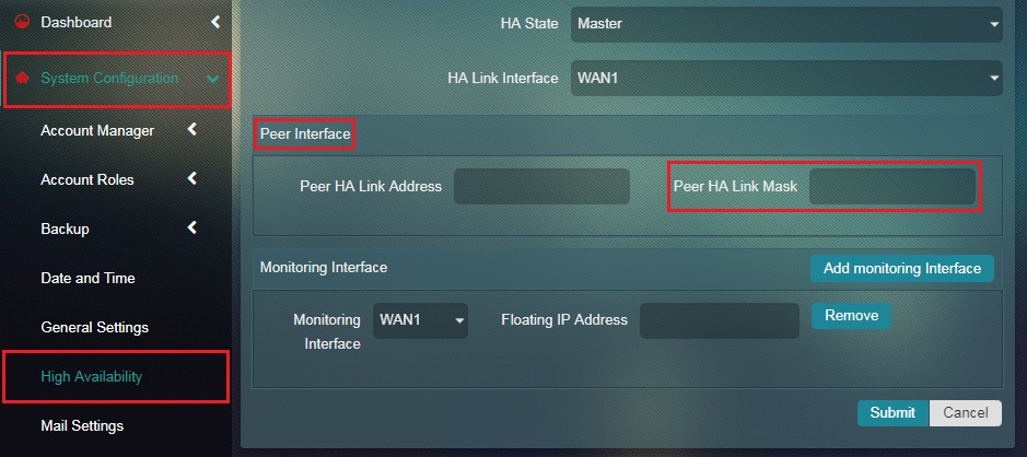
Step 8: Select WAN1 in the Monitoring Interface dropdown and enter the WAN1 Virtual IP Address in the Floating IP Address textbox under the Monitoring Interface section.
Note: The Monitoring Interface will be monitored for failures. If this interface goes down on MASTER node, the CE will change to BACKUP state. The Floating IP Address here is the Virtual IP address of WAN1 which is common for both Master CE and Backup CE. To know the Virtual IP address of WAN1, navigate to Network Control (in the Backup CE) > Infrastructure > IP Settings and view the WAN1 Virtual IP Address in the Network Interface section (highlighted below). In our case its 10.60.1.160. 
Step 9: Now click the Add Monitoring Interface. 
Step 10: You will now see a new monitoring interface column popping out in the Monitoring Interface section.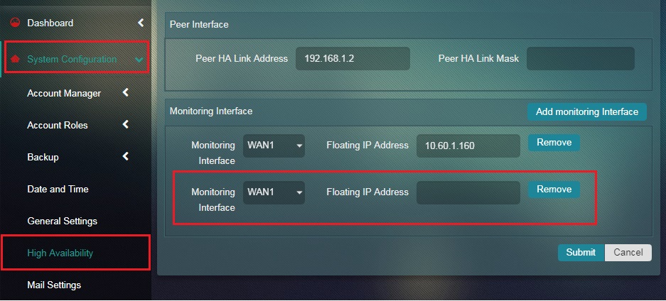
Step 11: Select LAN1 in the Monitoring Interface dropdown, enter the LAN1 Virtual IP Address in the Floating IP Address textbox and click the Submit button under the Monitoring Interface section.
Note: The Monitoring Interface will be monitored for failures. If this interface goes down on MASTER node, the CE will change to BACKUP state. The Floating IP Address here is the Virtual IP address of LAN1 which is common for both Master CE and Backup CE. To know the Virtual IP address of LAN1, navigate to Network Control (in the Backup CE) > Infrastructure > IP Settings and view the LAN1 Virtual IP Address in the Network Interface section (highlighted below). In our case its 10.60.1.100.
Step 12: The system will now show the Information Message, “HA Group Added Successfully”.
Note: You can also edit all the HA settings and configurations done in the Master CE. These details can be seen and edited in the HA Group Details section which comes up with the Information Message.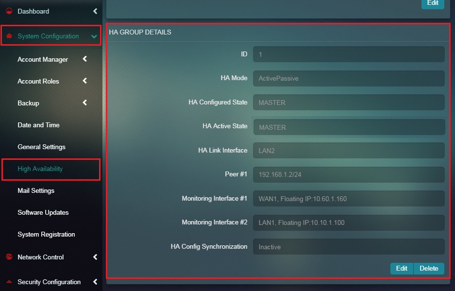
Step 13: If the Master CE has been successfully configured for High Availability set-up then you will see that the word ‘Master’ added next to the High Availability icon as shown below.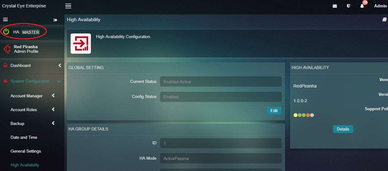
Note: If the fail-over system does not work due to any issues then the High Availability icon will be red.
Once the HA settings & configurations are done in the Master CE, similar settings are done in the Backup CE too. The settings involves creating a HA group which includes Selecting the HA State, Adding HA Link Interface, Adding Peer HA Link Address, Adding Peer HA Link Mask, Adding Monitoring Interface, Adding Floating IP Address and Adding Multiple Monitoring Interfaces.
How to Configure Backup CE for HA Setup?
Step 1: In the High Availability page, click the edit button under the Global Settings section.
Step 2: You will now see the editable version of the Global Settings section. Select Enable from the Config Status dropdown and click the Update button.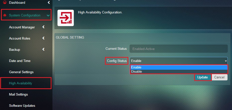
Note: Once High Availability Configuration Status is Enabled, the HA icon in the top left corner of the navigation menu will turn green as shown below. However, if the HA Configuration status is disabled then the High Availability icon turns grey.
Step 3: In the High Availability application page of the Backup CE, click the Add Group button.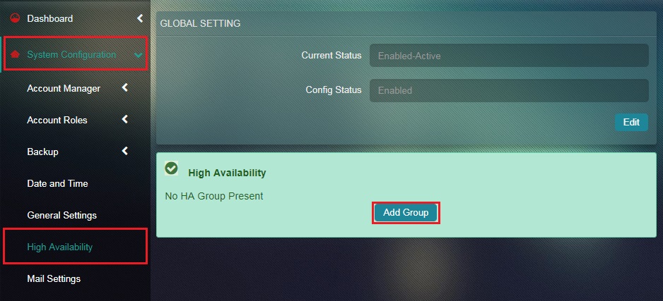
Step 4: You will now see the Add HA Group page. Select the HA State as Backup from the dropdown. 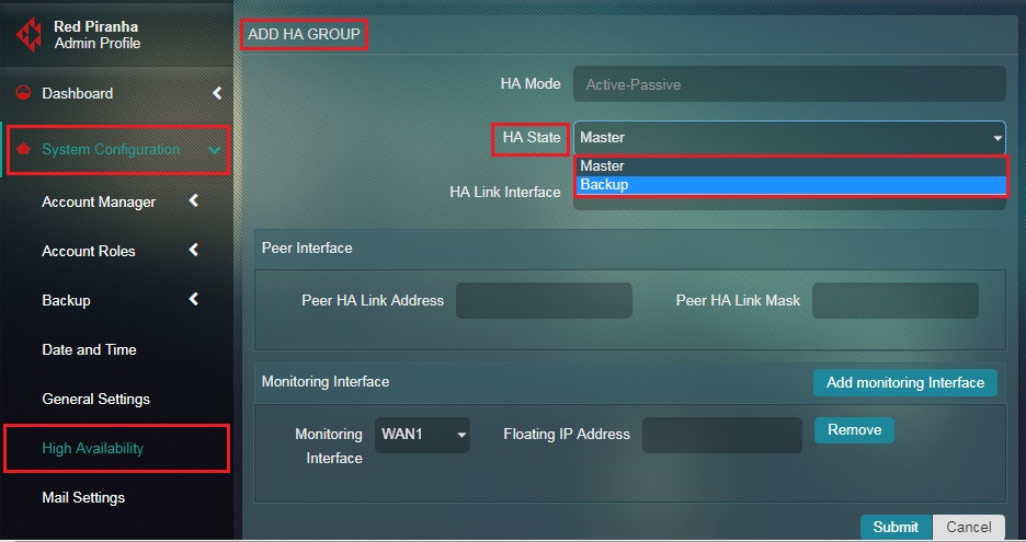
Step 5: Select HA Link Interface from the dropdown.
Note: The HA Link Interface here is the dedicated link interface between two CEs (in our case it’s LAN 2).
Step 6: Enter the Peer HA Link Address in the textbox under the Peer Interface section.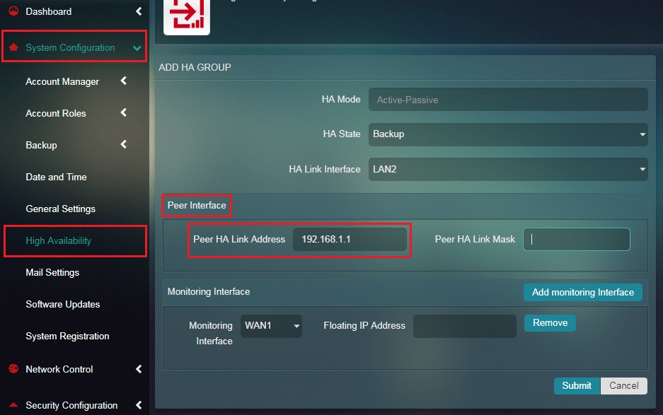
Note: The Peer HA Link Address here is the LAN2 IP address of the Master CE which can be found in the IP settings application under the Network Interface section of the Backup CE. To know the Peer HA Link Address here, navigate to Network Control (in the Master CE) > Infrastructure > IP Settings and view the LAN 2 IP address in the Network Interface section (highlighted below). In our case its 192.168.1.1
Step 7: Enter the Peer HA Link Mask in the textbox under the Peer Interface section.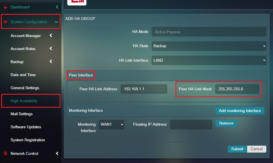
Step 8: Select WAN1 in the Monitoring Interface dropdown and enter the WAN1 Virtual IP Address in the Floating IP Address textbox under the Monitoring Interface section.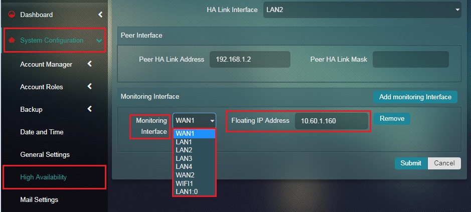
Note: The Monitoring Interface will be monitored for failures. If this interface goes down on MASTER node, the CE will change to BACKUP state. The Floating IP Address here is the Virtual IP address of WAN1 which is common for both Master CE and Backup CE. To know the Virtual IP address of WAN1, navigate to Network Control (in the Master CE) > Infrastructure > IP Settings and view the WAN1 Virtual IP Address in the Network Interface section (highlighted below). In our case its 10.60.1.160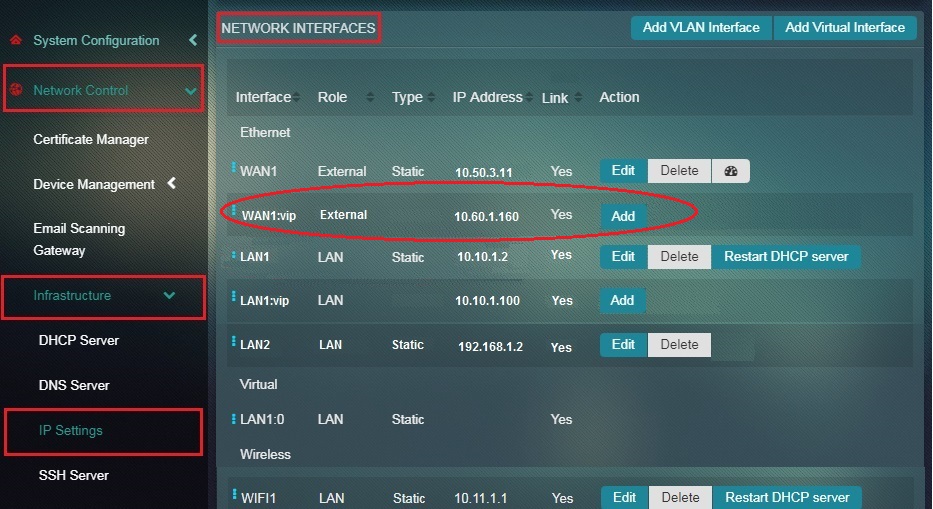
Step 9: Now click the Add Monitoring Interface.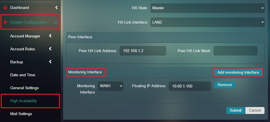
Step 10: You will now see a new monitoring interface column popping out in the Monitoring Interface section.
Step 11: Select LAN1 in the Monitoring Interface dropdown, enter the LAN1 Virtual IP Address in the Floating IP Address textbox and click the Submit button under the Monitoring Interface section. 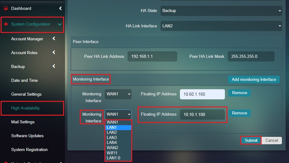
Note: The Monitoring Interface will be monitored for failures. If this interface goes down on MASTER node, the CE will change to BACKUP state. The Floating IP Address here is the Virtual IP address of LAN1 which is common for both Master CE and Backup CE. To know the Virtual IP address of LAN1, navigate to Network Control (in the Master CE) > Infrastructure > IP Settings and view the LAN1 Virtual IP Address in the Network Interface section (highlighted below). In our case its 10.60.1.100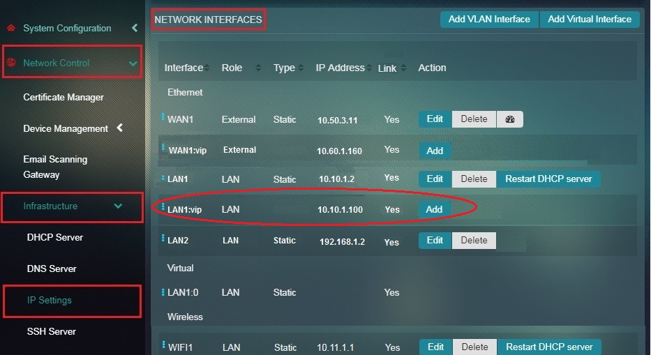
Step 12: The system will now show the Information Message, “HA Group Added Successfully”.
Note: You can also edit all the HA settings and configurations done in the Backup CE. These details can be seen and edited in the HA Group Details section which comes up with the Information Message.
Step 13: If the Backup CE has been successfully configured for High Availability set-up then you will see that the word ‘Backup’ is added next to the High Availability icon.
Note: If the fail-over system does not work post configurations then the High Availability icon will be red.