IPSec VPN
Crystal Eye’s IPSec VPN application enables administrators to create encrypted tunnels between two nodes or sites further enabling secure communications. These tunnels can be configured to support IPSec Host-to-Host and IPSec Site-to-Site network connections. The sole aim of using IPSec VPN is to establish secure connections between two hosts or two networks (example two office branches).
Left-hand Navigation Panel > Network Control > SD WAN > IPSec VPN 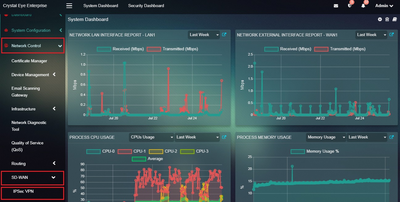 |
|---|
Crystal Eye’s IPSec VPN application plays a vital role in establishing secure connections between two nodes. Such a connection is made possible by creating an IPSec Host-to-Host Tunnel between two Crystal Eye appliances which can be easily done with the help of CE’s IPSec VPN application.
IPSec Host-to-Host VPN can be explained with the help of the following sample setup:
Before starting with the configuration of an IPsec host-to-host VPN tunnel, two working Crystal Eye appliances are required or (one CE and any other Device that supports IPsec Host-to-Host VPN). Another requirement is that both the hosts must be connected to the internet.
For the sample configuration we use two Crystal Eye appliances to stimulate an IPSec host-to-host tunnel, with the following configurations:
| Configuration | Host A/Crystal Eye Appliance 1 | Host B/Crystal Eye Appliance 2 or IPSec VPN Supported Device |
|---|---|---|
| WAN IP | 239.171.187.234 | 203.171.195.256 |
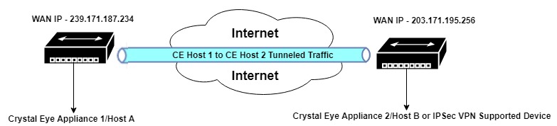
In the diagram above, Crystal Eye Appliance 1 is Host A with a WAN IP address 239.171.187.234 and Crystal Eye appliance 2 is Host B (or any device that supports IPSec VPN) with a WAN IP address 203.171.195.256. Both the hosts are connected to each other through an IPSec hot-to-host VPN tunnel and are also connected to the internet.
While creating an IPSec host-to-host VPN connection the first step involves gathering WAN IP address of both the hosts which can be attained easily in the IP Settings application (look for Network Interface section).
Note: The configuration settings must be done on both Host A (Crystal Eye Appliance 1) and Host B (Crystal Eye Appliance 2) in order to successfully establish an IPSec Host-to-Host Tunnel between them.
The other details that the administrator is required to enter while configuring an IPSec Host-to-Host Tunnel are, Connection Name, Connection Policy Mode (Listen or Automatic), Connection Type (Tunnel or Transport), Connection Mode, Local WAN IP, Remote WAN IP and the Pre-shared Key.
How to Configure IPSec Host-to-Host Tunnel to Connect Host A & Host B?
| Host ‘A’ Configuration |
|---|
Step 1: In the IPSec VPN application page, click the Enable button in the IPSec VPN Status section. 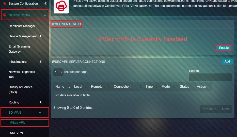
Note: When IPSec Host-to-Host VPN is disabled, CE does not allow any input traffic of IPSec protocols such as ESP, AH, and UDP 500. So when IPSec is enabled, CE allows IPSec traffic and adds required firewall rules into the system.
Step 2: You will now see the message IPSec VPN is Currently Enabled. Click the Add button under IPSec VPN Server Connections section. 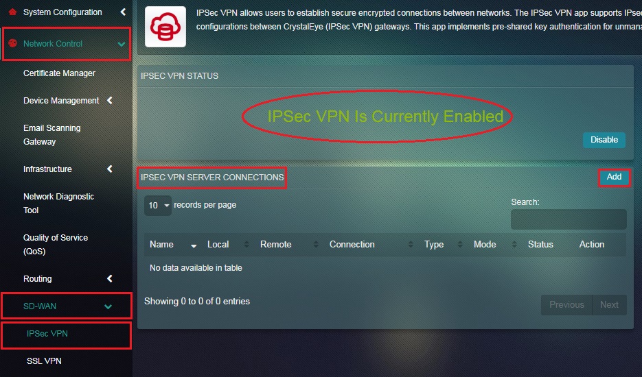
Step 3: You will now be directed to the Settings page. Select Host-to-Host from the Mode dropdown under the General Settings section. 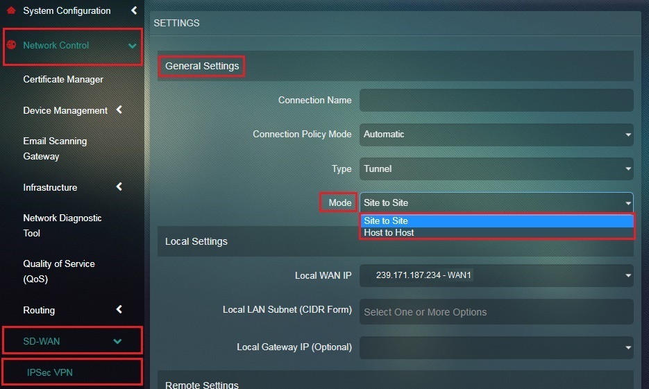
Step 4: Enter a nickname for the intended host-to-host tunnel in the Connection Name textbox.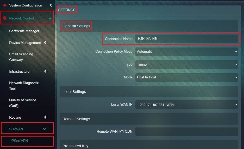
Step 5: Select Automatic from the Connection Policy Mode dropdown.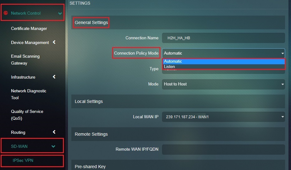
Step 6: Select Tunnel from the Connection Type dropdown. 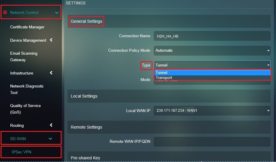
Step 7: Select the Local WAN IP of host A or Crystal Eye appliance 1 from the dropdown. 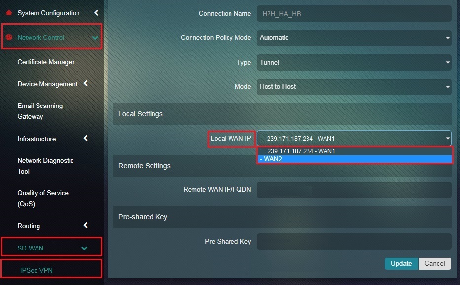
Step 8: Enter the WAN IP address of Host B in the Remote WAN IP/FQDN textbox. 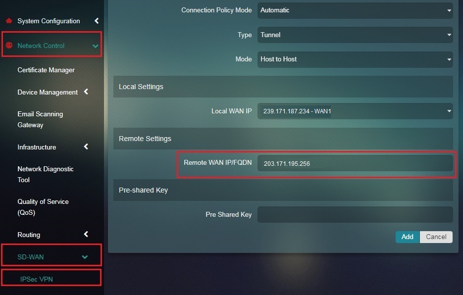
Note: The Remote WAN IP address or the WAN IP of Host B can be viewed in the Network Interface section of the IP Settings application of the Crystal Eye appliance 2.
Step 9: Enter the Pre-shared Key in the textbox and click the Add button.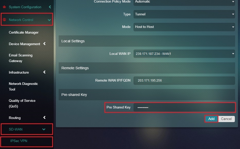
Note: The pre-shared key must be identical for host A and host B.
You will now see the IPSec VPN Server Connection details as shown in the screenshot below. 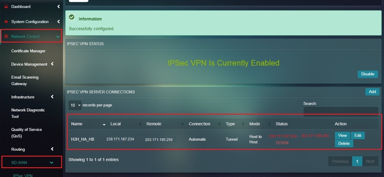
Note: You may notice that since we haven’t configured host B for IPSec Host-to-Host tunnel, the Status under the IPSec VPN Server Connection section shows that it’s Down.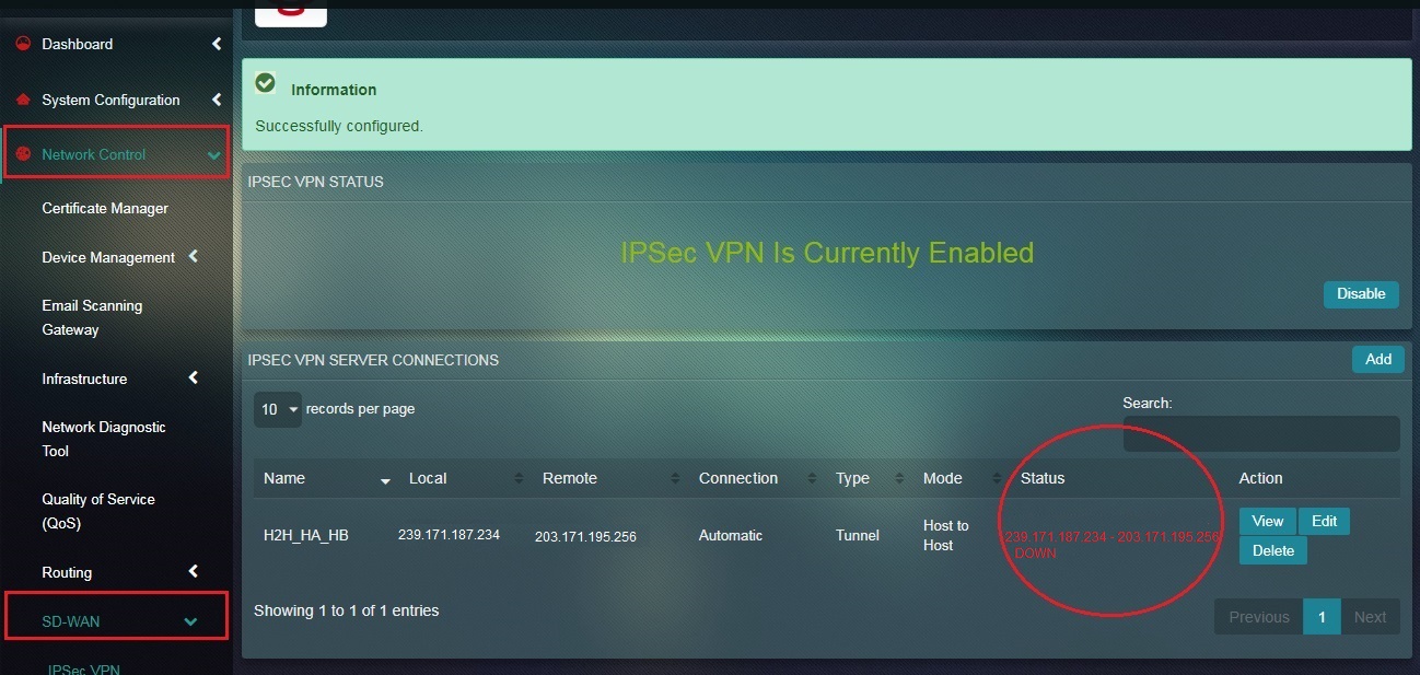
| Host ‘B’ Configuration |
|---|
Step 11: Enable IPSec VPN under IPSec VPN Status section.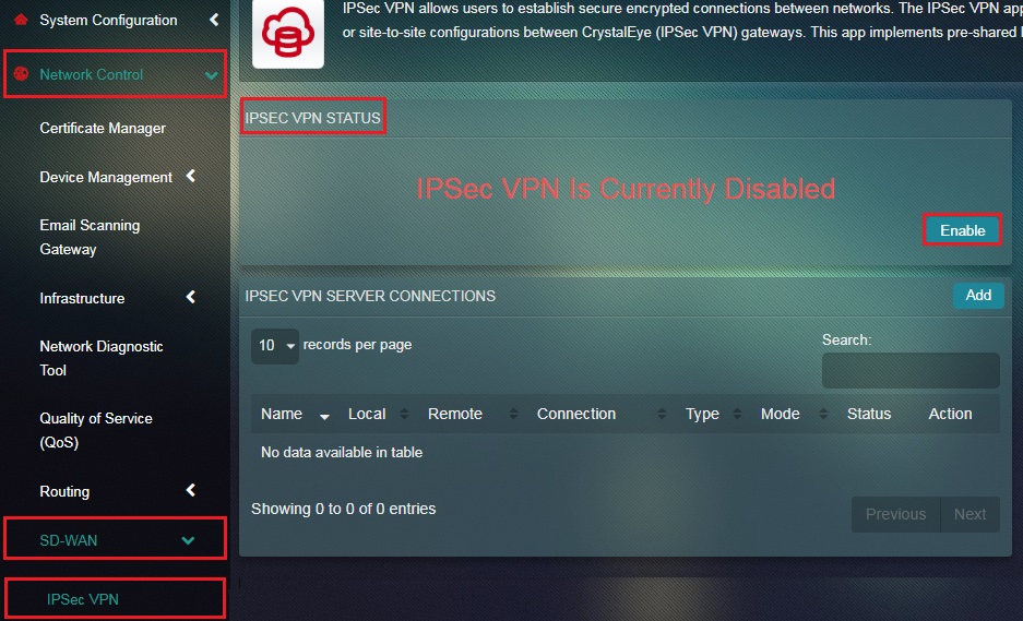
Step 12: You will now see the message IPSec VPN is Currently Enabled. Click the Add button under IPSec VPN Server Connections Section.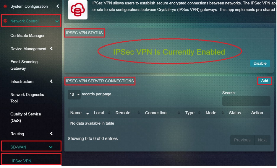
Step 13: You will now see the Settings page. Select Host-to-Host from the Mode dropdown.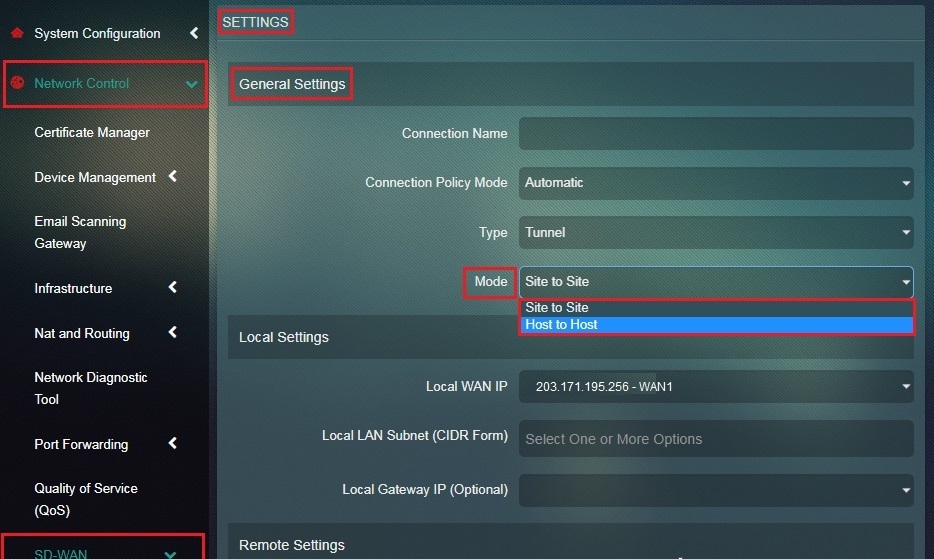
Step 14: Enter the assigned nickname of the host-to-host tunnel in the Connection Name textbox. 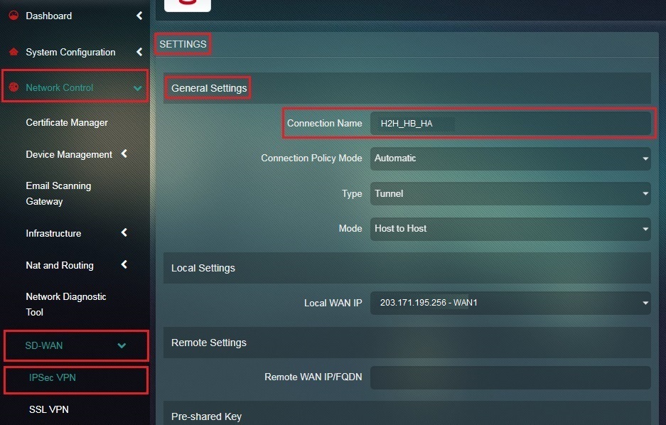
Step 15: Select Automatic from the Connection Policy Mode dropdown. 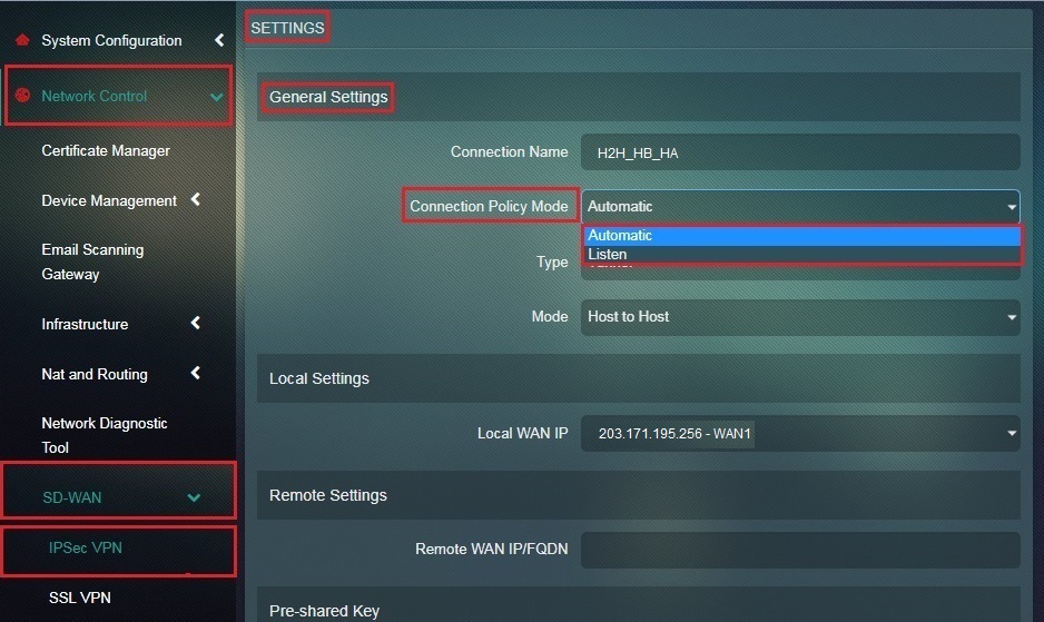
Step 16: Select Tunnel from the Connection Type dropdown.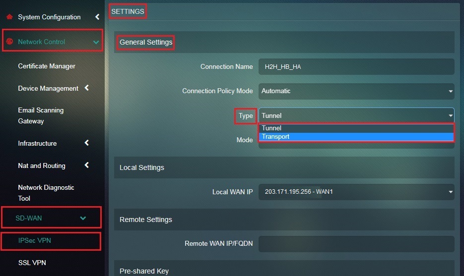
Step 17: Select the Local WAN IP of Host B or Crystal Eye 2.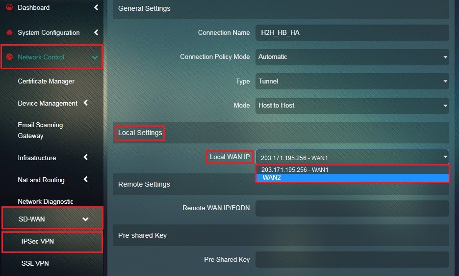
Step 18: Enter the Remote WAN IP or the WAN IP of Host A/ Crystal Eye appliance 2 in the textbox.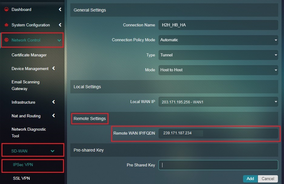
Step 19: Enter the Pre-shared Key in the textbox and click the Add button.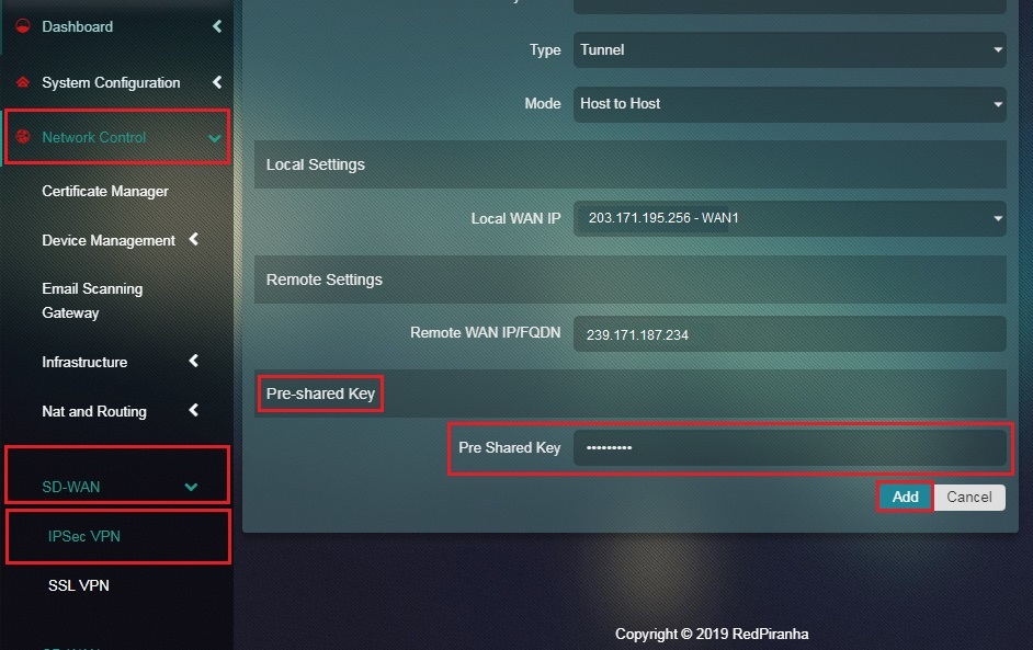
Note: Ensure that the key entered here is identical to the one assigned for Host A/Crystal Eye appliance 1.
You will now see the IPSec VPN Server Connection details as shown in the screenshot below. 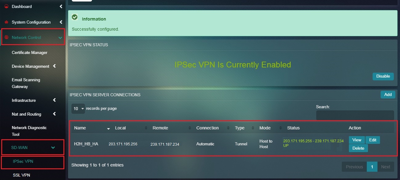
Note: You will notice that the Status under the IPSec VPN Server Connection section shows that it’s UP. 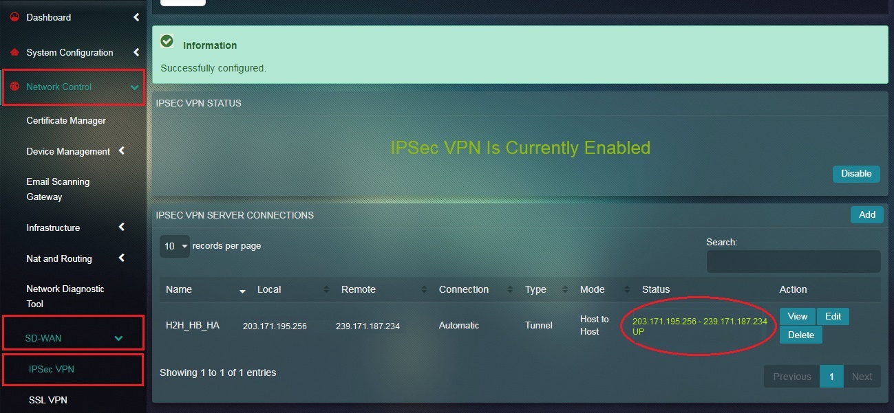
An IPSec Site-to-Site VPN allows offices in multiple fixed locations to establish secure connections with each other over a public network such as the internet. IPSec Site-to-Site VPN extends the company’s network, making computer resources from one location available to employees at other locations. The best example of a company that needs an IPSec Site-to-Site VPN could be a growing cooperation with dozens of branch offices across the globe. If a company has one or more remote locations that they wish to join in a single private network, they can create an intranet VPN to connect each separate LAN to a single WAN.
IPSec Site-to-Site VPN can be explained with the help of the following sample setup:
Before starting with the configuration of an IPSec Site-to-Site VPN tunnel, two working Crystal Eye appliances are required or (one CE and any other device that supports IPSec Site-to-Site VPN) with a unique LAN IP subnet for each side of the connection (LAN subnets must be different from the LAN subnets of the remote network). Another requirement is that both the hosts must be connected to the internet.
For the sample configuration we use two Crystal Eye appliances to stimulate an IPSec site-to-site tunnel, with the following configurations:
| Configuration | Site A | Site B |
|---|---|---|
| WAN IP | 203.198.111.106 | 239.209.112.100 |
| LAN 1 | 10.106.1.0/24 | 10.105.1.0/24 |
| LAN 2 | 10.116.1.0/24 | 10.205.1.0/24 |
| LAN 3 | 10.216.1.0/24 | N/A |
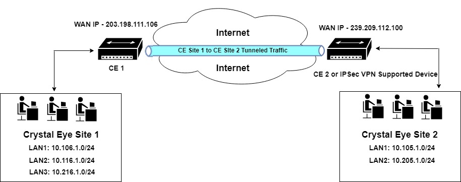
In the diagram above, the WAN IP of CE 1 is 203.198.111.106 and the WAN IP of CE 2 is 239.209.112.100. Both the sites namely, Crystal Eye Site 1 and Crystal Eye Site 2 are connected to each other through an IPSec Site-to-Site VPN tunnel.
While creating an IPSec site-to-site VPN connection the first step involves gathering WAN IP address of Site 1 and Site 2.
Note: The configuration settings must be done on both CE 1) and CE 2) in order to successfully establish an IPSec Site-to-Site Tunnel between the two sites.
The other details that the administrator is required to enter while configuring an IPSec Site-to-Site Tunnel are, Connection Name, Connection Policy Mode (Listen or Automatic), Connection Type (Tunnel or Transport), Connection Mode, Local WAN IP, Remote WAN IP and the Pre-shared Key.
How to Configure IPSec Site-to-Site Tunnel to Connect Site 1 & Site 2?
| ‘Site 1’ Configuration |
|---|
Step 1: In the IPSec VPN application page, click the Enable button in the IPSec VPN Status section.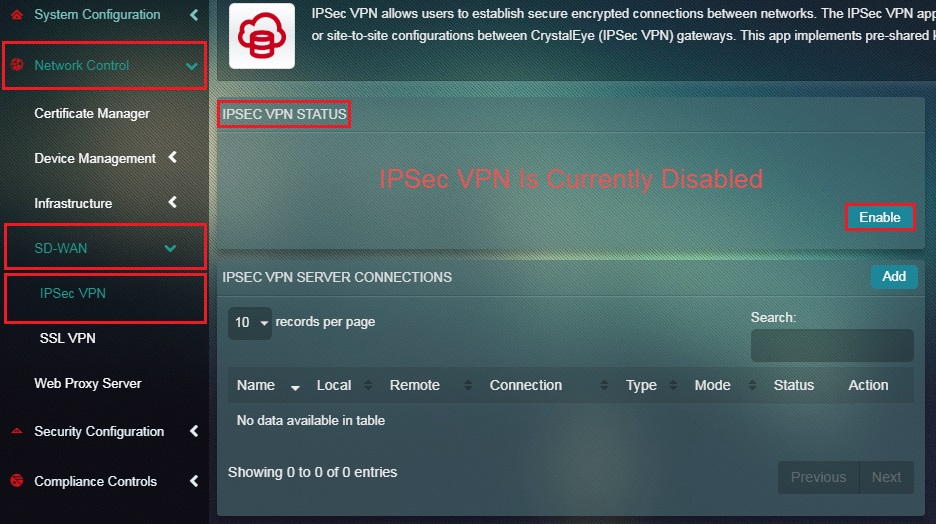
Note: When IPSec Site-to-Site VPN is disabled, CE does not allow any input traffic of IPSec protocols such as ESP, AH, and UDP 500. So when IPSec is enabled, CE allows IPSec traffic and adds required firewall rules into the system.
Step 2: You will now see the message IPSec VPN is Currently Enabled. Click the Add button under IPSec VPN Server Connections.
Step 3: You will now be directed to the Settings page. Select Site-to-Site from the Mode dropdown under the General Settings section.
Step 4: Enter a nickname for the intended site-to-site tunnel in the Connection Name textbox. 
Step 5: Select Automatic from the Connection Policy Mode dropdown.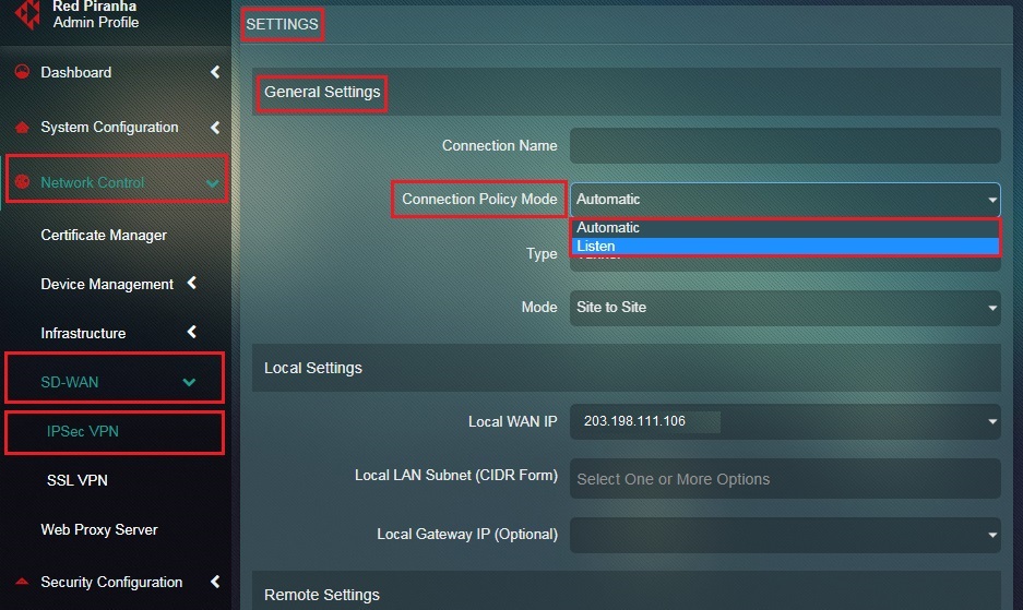
Step 6: Select Tunnel from the Connection Type dropdown.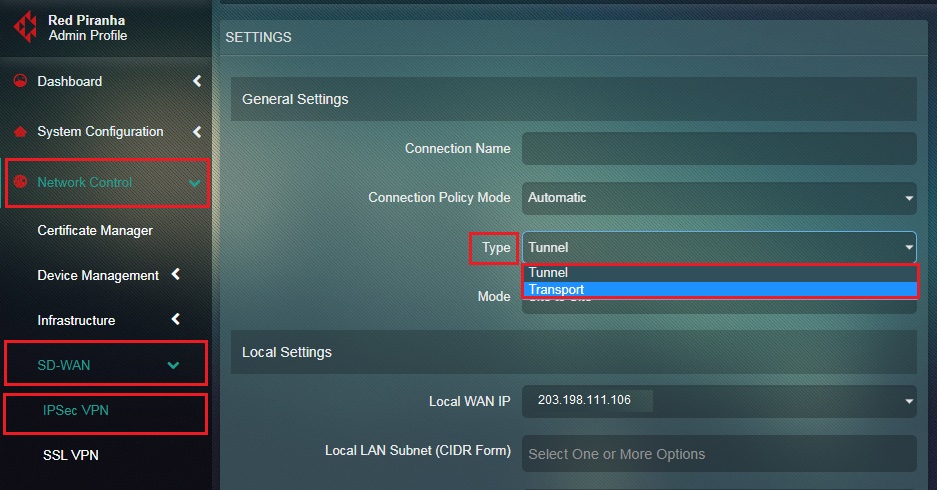
Step 7: Select the Local WAN IP of Site 1 from the dropdown.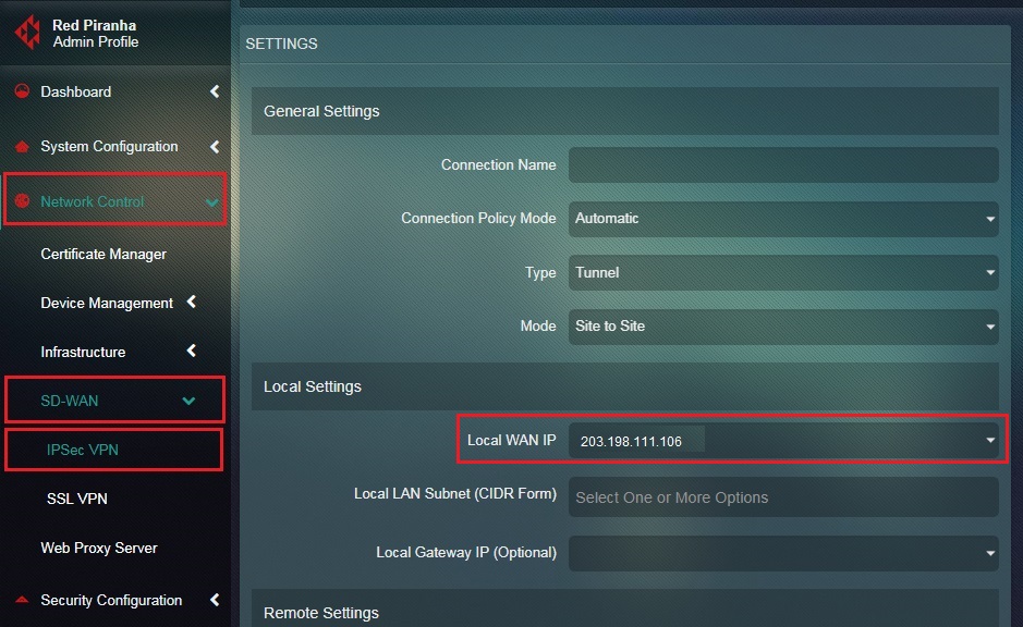
Step 8: Select the Local LAN Subnet from the dropdown which needs to be included in the Site-to-Site VPN.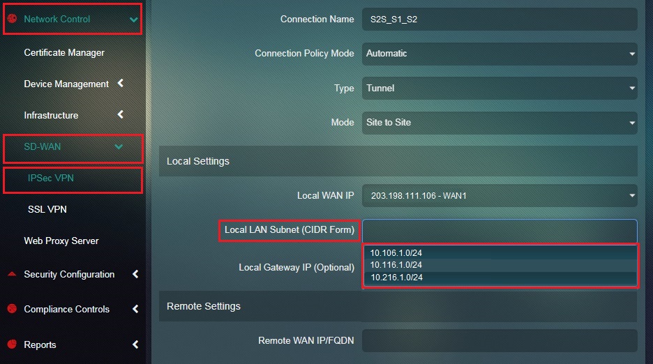
Step 9: Enter the Remote WAN IP or the WAN IP address of Site 2 in the textbox.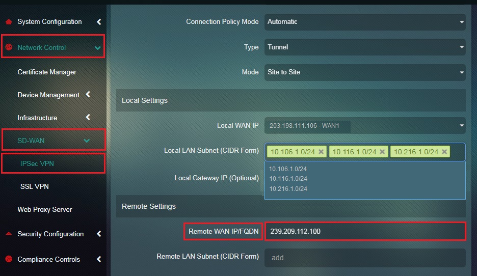
Step 10: Enter the Remote LAN Subnet or the LAN subnets on Site 2 in the textbox.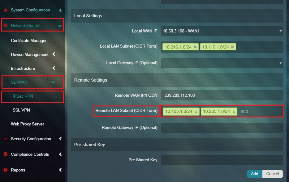
Step 11: Enter the Pre-shared Key in the textbox and click the Add button. 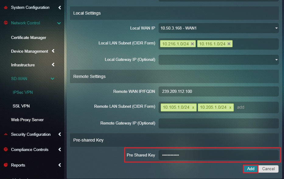
Note: The Pre-shared Keys must be identical for both Site 1 & Site 2 configurations.
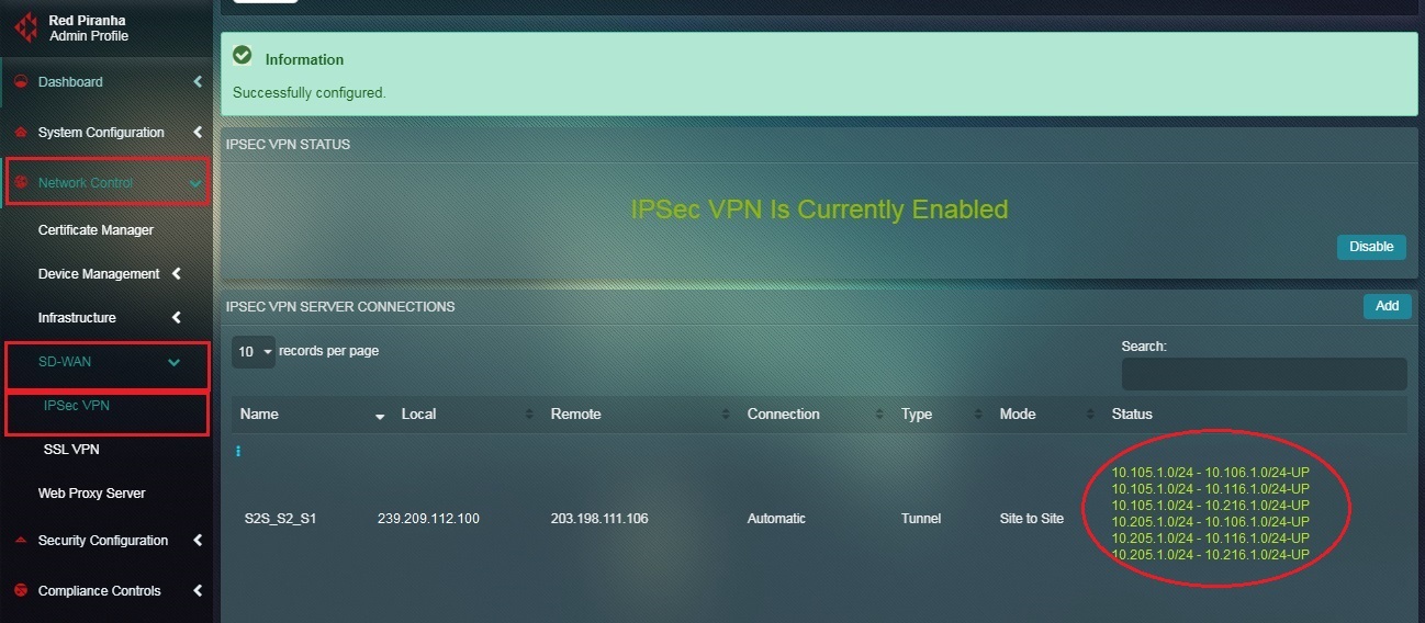
You will now see the IPSec Site-to-Site VPN Server Connection details as shown in the screenshot below.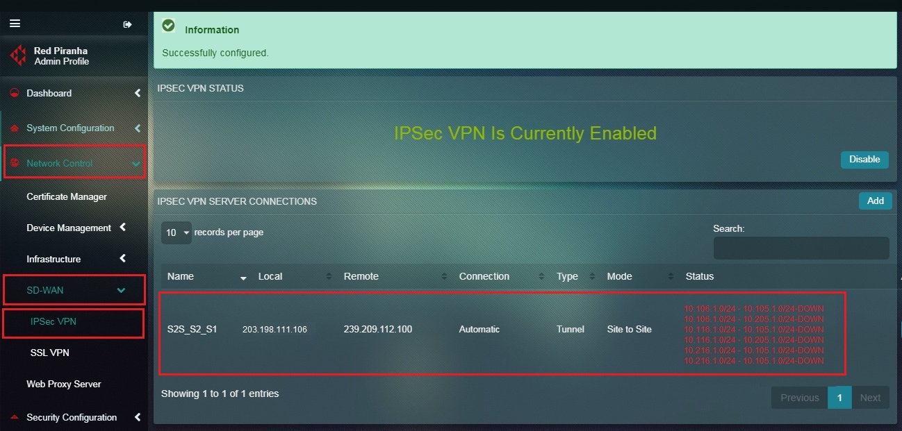
Note: You may notice that since we haven’t configured Site 2 for IPSec Site-to-Site tunnel, the Status under the IPSec VPN Server Connection section shows that it’s Down.
| ‘Site 2’ Configuration |
|---|
Step 13: Enable IPSec VPN under IPSec VPN Status section.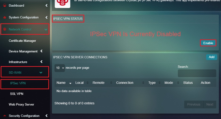
Step 14: You will now see the message IPSec VPN is Currently Enabled. Click the Add button under IPSec VPN Server Connections section.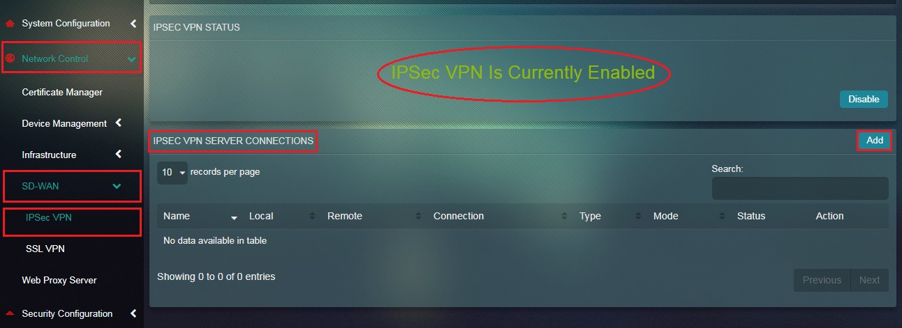
Step 15: You will now see the Settings page. Select Site-to-Site from the Mode dropdown.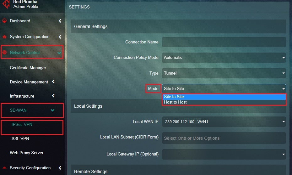
Step 16: Enter the assigned nickname of the site-to-site tunnel in the Connection Name textbox.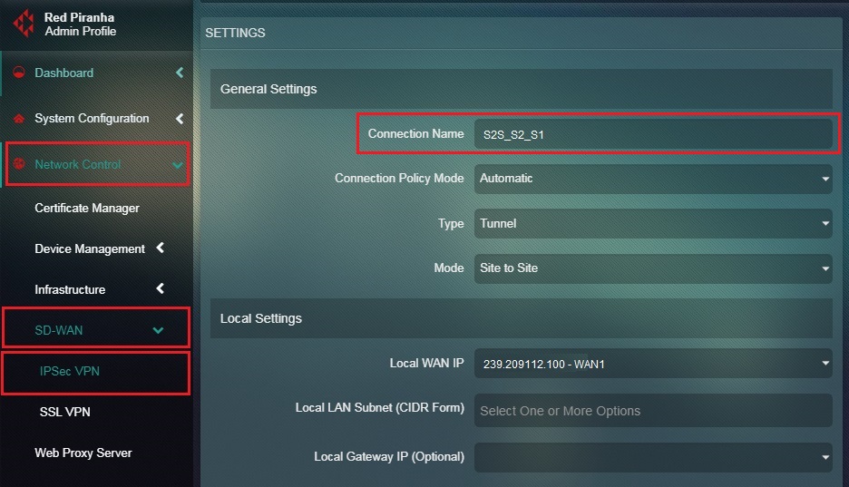
Step 17: Select Automatic from the Connection Policy Mode dropdown. 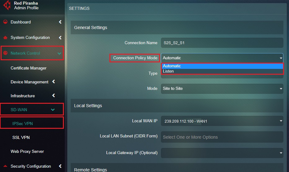
Step 18: Select Tunnel from the Connection Type dropdown.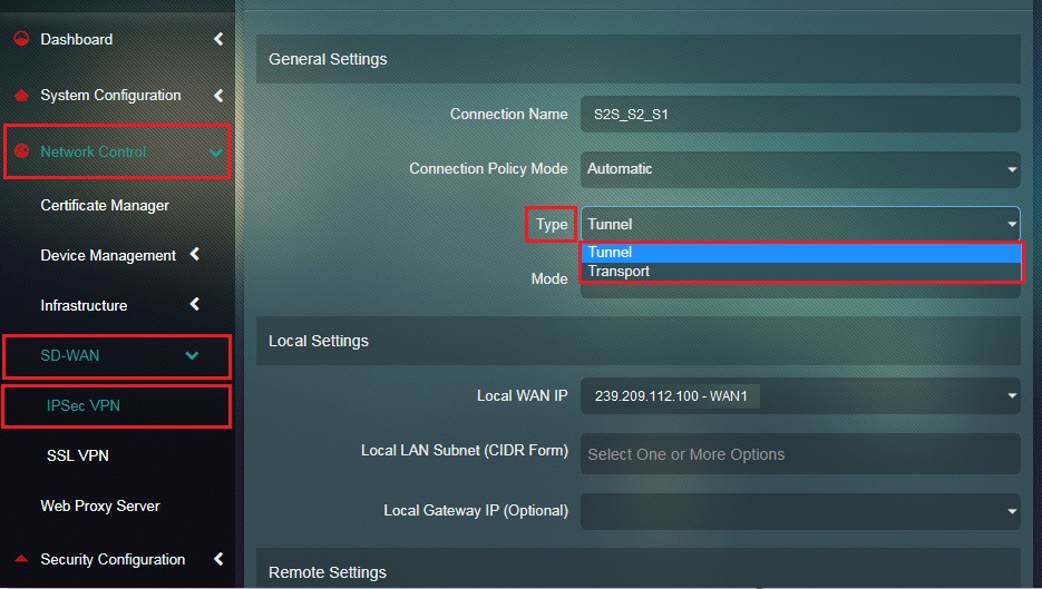
Step 19: Select the Local WAN IP of Site 2. 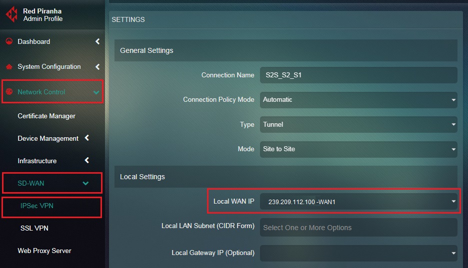
Step 20: Select the Local LAN Subnet from the dropdown which needs to be included in the Site-to-Site VPN .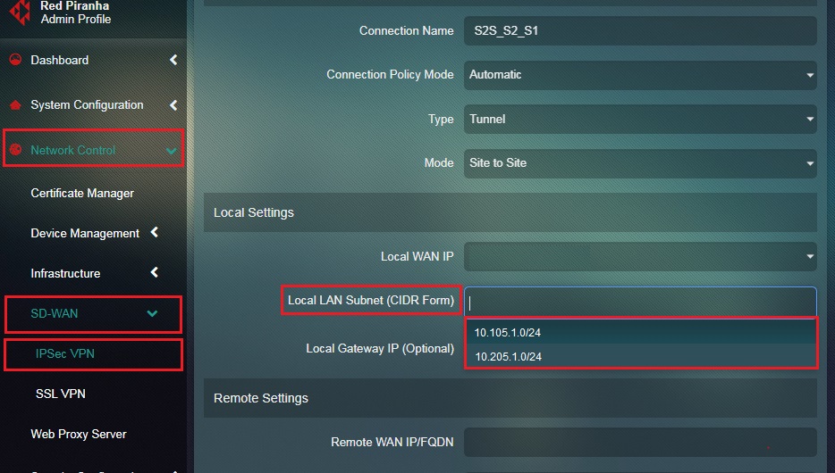
Step 21: Enter the Remote WAN IP or the WAN IP address of Site 1 in the textbox.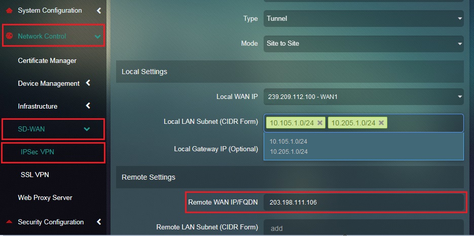
Step 22: Enter the Remote LAN Subnet or the LAN subnets on Site 1 in the textbox.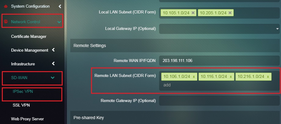
Step 23: Enter the Pre-shared Key in the textbox and click the Add button. 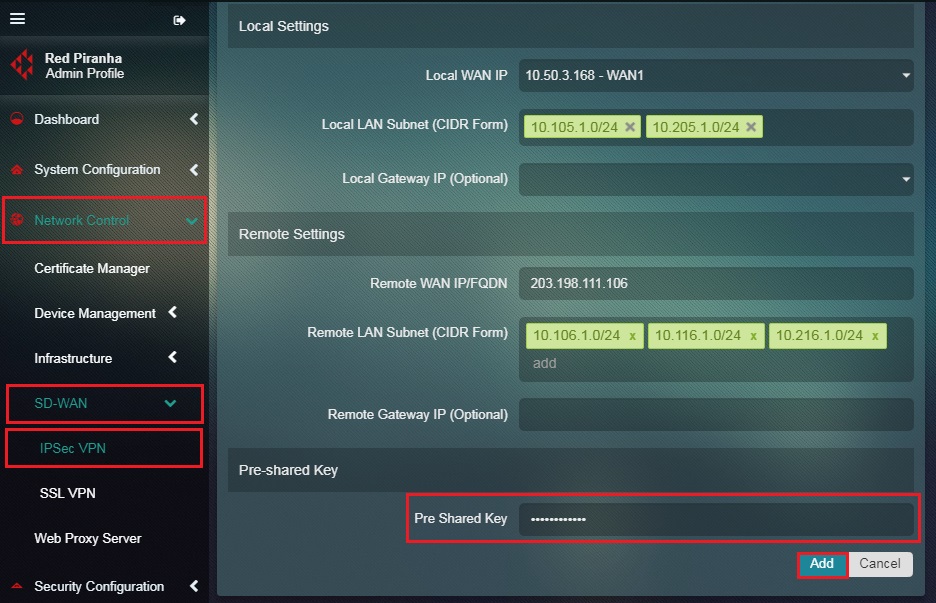
Note: The Pre-shared Keys must be identical for both Site 1 & Site 2 configurations.
You will now see the IPSec Site-to-Site VPN Server Connection details as shown in the screenshot below.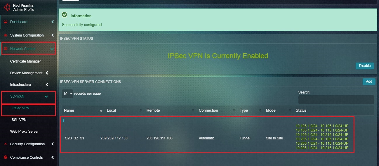
Note: You will notice that the Status under the IPSec VPN Server Connection section shows that it’s UP.